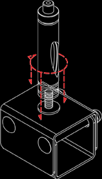
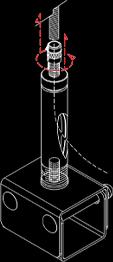
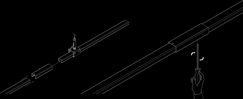
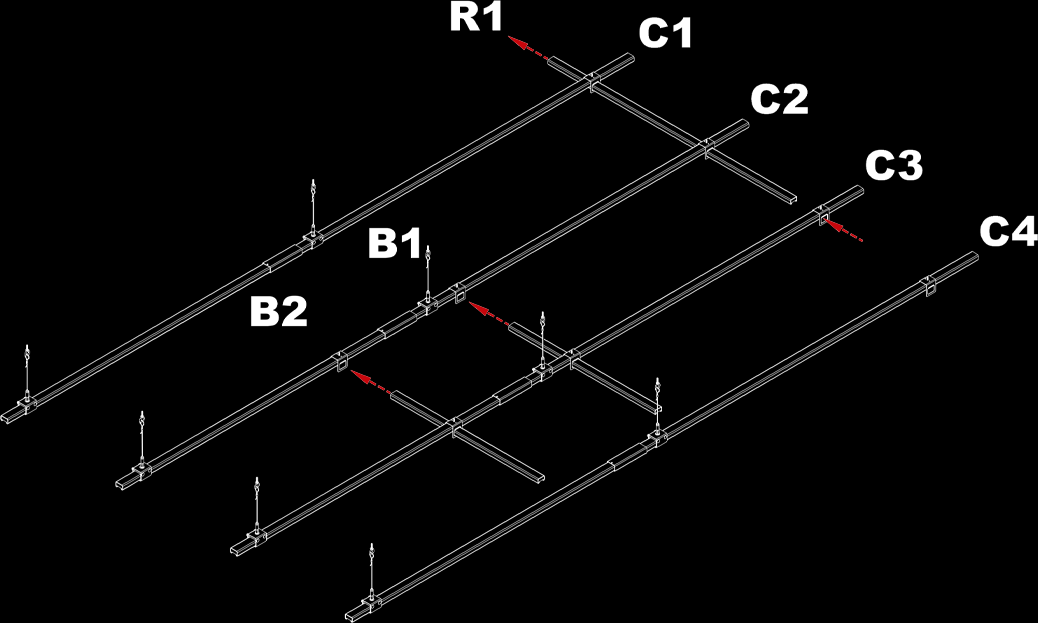
Typical installation for busSTRUT

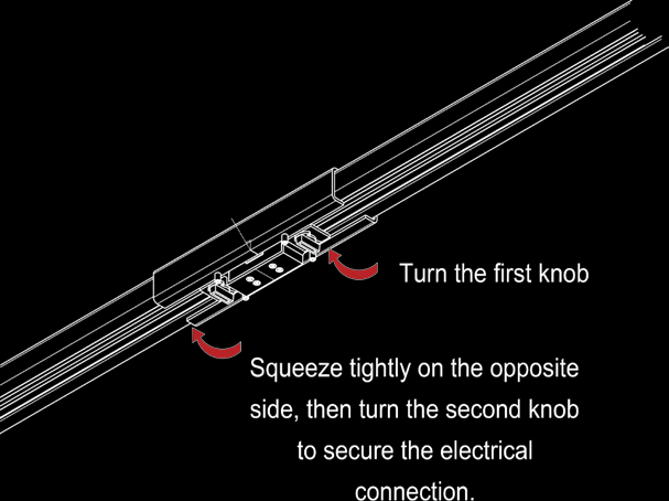
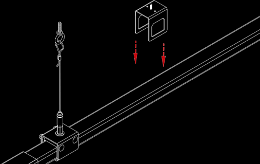
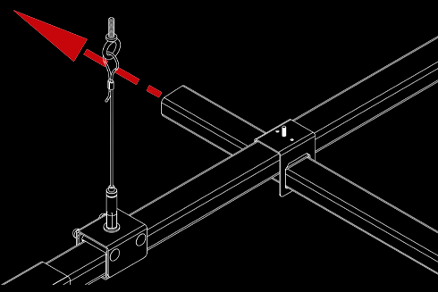
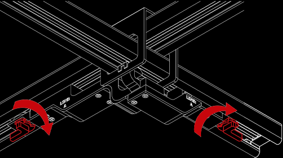
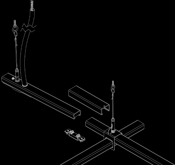
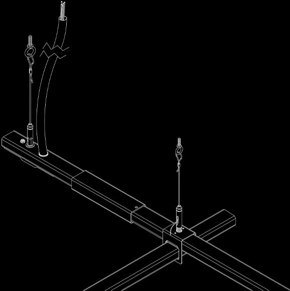
The steel bus duct channels are first suspended and aligned, then connected using joiners. Intersections are created with crossovers for flexible layouts, and the system is electrified with slimline jumpers for power distribution.

1

Suspending
busSTRUT

Red 2

Joining
busSTRUT

Red 3

Intersecting
busSTRUT

Red 4

Electrifying
busSTRUT

STEP 1 Suspending busSTRUT

How to suspend busSTRUT Track Busway

To suspend busSTRUT, begin by attaching cable asembly to structure. Next, assemble hangers and attach cable glide. After assembling the hangers, feed the cables through glide to attach. Slide busSTRUT track busway through suspended hangers. Finally, level busSTRUT and trim cable. See video and illustrations for more detail on suspending busSTRUT track busway.

suspend busstrut cables graphic

Suspend Cables

Attach cable Assembly to structure. It is the contractor and/or engineer’s responsibility to determine correct connection to structure (beam clamp, etc).

Assemble busstrut Hangers Graphic

Assemble Hangers

Assemble Hangers and attach cable glide.

Attach busstrut hangers to cables graphic

Attach Hangers to Cables

Feed cables through glide to attach.

Assemble

Create cable suspended runs of busSTRUT track busway. Usually, these are running perpendicular to structural joists. Insert busSTRUT lengths through hangers/crossovers working from finished height.

assemble busstrut graphic

Level & Trim

Level busSTRUT track busway and trim cable leaving enough pass through cable for future leveling.

Level & Trim busSTRUT track busway graphic

STEP 2 Joining busSTRUT

How to use Joiners

Joiners are used to mechanically and electrically connect individual busSTRUT track busway lengths. Attach joiners to each end of connecting busSTRUT. See video and illustrations for more detail on how to use busSTRUT joiners.

Insert & Tighten Joiners

Attach joiners then tighten set screws on the bottom of the joiner. Joiners require 3/32 Hex key for tightening set screws.

Insert and tighten joiners

Attach Insert

Line up center of insert with etched centerline on joiner sleeve. A joiner insert is a single piece unit that is installed with two knobs, one must be fully turned in each abutting length. As a result power can continue to flow from one length to the next.

Attach Insert Graphic

STEP 3 Intersecting busSTRUT

Installing Crossovers Dropping On

Crossovers can be dorpped onto suspended busSTRUT track busway to create intersections. See video and illustrations for more detail on how to use busSTRUT crossovers.

Add Crossover

Crossovers can be dorpped onto suspended busSTRUT track busway to create an intersection with a perpendicular run of busSTRUT.

Add busstrut crossover graphic

Perpendicular Runs

Slide perpendicular runs of busSTRUT track busway through the crossover and tighten the set screws.

Perpendicular busstrut runs graphic

Create Desired Setup

Perpendicular runs can create a full grid or be short bridges which are easily moved into the desired position.

Create Desired busSTRUT Setup Graphic

STEP 4 Electrifying busSTRUT

busSTRUT Jumpers

Slimline Jumper (MD2020-UNIV-IJ-B-X) is a single piece unit allowing power to flow from one length of busSTRUT track busway to the next. See the video and directions below to learn how to install slimline jumpers.

Slimline Jumper

A single piece unit that is installed with two knobs, one must be fully turned in each abutting length. As a result, power can continue to flow from one length to the next.

Slimline Jumper

Proper Setup

Make sure that the slimline crossover is tightened before attaching the slimline jumper.

Proper Setup

Clip to Crossover

First, clip the jumper to the crossover.

Clip to Crossover

Seat the Jumper

Seat the jumper into the busSTRUT track busway by squeezing tightly on one side and turning the knob. Then, turn the other knob to complete the circuit.

Seat the Jumper

Starter Feed

This 16” length supplies power to a configuration from the preassembled cord and to the abutting length via a joiner insert that must be installed.

Starter Feed

The Starter Feed is a 16” power supply and comes with a 1/4-20 Stud to create an additonal hang point and a 15’ 15/4 SOOW Cord to connect power to the system. Attach the cable glide to the stud and tighten. Connect the aircraft cable as shown in Step 1.

busstrut starter feed

Connecting the Starter

Once the starter is properly suspended, connect the starter to the suspended grid using a Joiner and Insert as shown in step 2. Connect SO Cord to power the system.

busstrut connecting the starter